3D X-ray computed tomography for evaluation and quality control of injection-moulded parts
Ensuring the quality of injection-moulded parts is challenging because the process varies over time. 3D X-ray computed tomography is powerful for evaluating the quality of fibre-reinforced parts.
A company used injection-moulded brackets in hundreds of thousands of machines every year. The company experienced periods of increased failure rates of their brackets and contacted FORCE Technology for help. Non-destructive testing using 3D X-ray computed tomography proved to be a great solution for determining the origin of the failures.
Failing brackets
The material chosen for the brackets is Grilon BG-30 – a glass fibre-reinforced polyamide chosen for high stiffness and strength. The brackets are designed so that one end is fastened with a bolt, and in the other end, a load-bearing strap is attached to a strap bar.
The failure mode for the brackets is breakage at the point marked with a red circle in the photo below. The failure occurs when load is applied to the bracket.
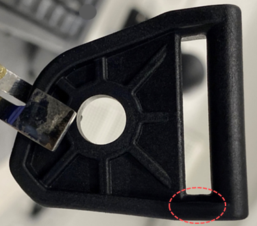
The cost of the part is low, but replacing the bracket is very time-consuming and thus an expensive and highly undesirable operation.
Optical inspection and destructive testing
Brackets like these are usually investigated through optical inspection. Because of the fibre reinforcement, the material is unsuitable for cutting, so breaking of pristine brackets is the preferred method during inspection – in other words destructive testing.
As the material is fibre-reinforced, the surface at the break will contain many fibres attached to one part of the break, which have been extracted from the other side. This results in a porcupine-like surface.
It is difficult to quantify how much of the holes visible from the surface was present before the break, and how much of the holes is the result of extraction of fibres. As with any cutting method, this also only provides information about the volume around the break surface.
3D CT scanning for non-destructive testing
To complement the investigations, the brackets were scanned using 3D X-ray computed tomography. This method provides a full 3D dataset, corresponding to 1000 virtual slices through the bracket.
The vacuum voids inside the bracket are easily identifiable. Marking the vacuum voids with blue and making the rest of the bracket semi-transparent, it is possible to see where and how many vacuum voids are present in the bracket.
The voids provide no strength to the brackets, and all the fibres that cross through the voids are also compromised in their ability to provide the expected strength. From the images above, the origin of the increased failure rate is seen clearly.
It is concluded that the process parameters of the injection moulding have changed over time, so that excessive amounts of vacuum voids are present. These voids lead to reduced strength, which again results in increased failure rates.
With this knowledge, the customer could go back and work on process optimisation directed at reducing vacuum voids in the injection process. The images also show that vacuum voids are present even when the production is considered normal.
In this case, 3D X-ray computed tomography provided a non-destructive method for evaluation of the injection moulding process quality and thus the strength of the bracket. 3D X-ray computed tomography could be implemented for quality control periodically or even at batch level for these critical brackets.

Related services

Advanced surface characterisation and analysis
Investigation and analysis of surfaces, structures, fractured surfaces, particles, impurities etc.
Facility