Bridge aerodynamics
With increasing pressure to improve infrastructure throughout the world, bridge constructions is are constantly experiencing engineering challenges.
Technological developments allow bridges to be constructed longer and lighter than previously attempted. The limitations on the span of bridges are being pushed continuously. Further, many bridges are designed as landmark structures with challenging architectural and structural features. Aerodynamic tests in a wind tunnel are therefore crucial for both safety and longevity.
Section model tests in a wind tunnel
The crucial part of all large bridges in terms of aerodynamics is the bridge deck. This is especially true for flexible bridge structures such as suspension bridges and cable-stayed bridges.
The aerodynamic behaviour of a bridge deck can be studied by use of a section model. Section models represent an appropriate part of the bridge deck.
Section model tests ensure a favourable deck cross section by establishing:
- Design loads such as drag, lift and overturning moment (CD, CL & CM)
- Aerodynamic stability limits for flutter and galloping within design limits
- Acceptable buffeting motions
- Limited vortex induced motion for fatigue and user comfort
Should the aerodynamic behaviour of the deck be beyond the acceptable limits, geometrical changes can easily be introduced to improve the deck’s aerodynamic behaviour. Also remedial measures such as dampers and guide vanes can be investigated.
Wind tunnel testing of free standing pylons
The erection of a bridge pylon is a critical activity as the cables and deck are not present to prevent excessive lateral or torsional motions and base-bending moments. It is therefore common to ensure the safety of this construction stage by wind tunnel testing.
Wind tunnel tests of pylons may include static load tests with a static force balance and/or aeroelastic model tests of various construction stages or the completed free-standing pylon. Static tests provide the static force coefficients to determine the static deflection.
Aeroelastic model tests give a complete description of the dynamic response of the pylon to wind, accurately reproducing the actual bridge pylon response to natural wind in the wind tunnel. Also this enables the designer to assess possible vortex induced motion and aerodynamic instabilities such as galloping.
Aeroelastic full bridge model tests
The overall response of the complete bridge to wind loading can be accurately determined by full bridge aeroelastic model tests only. Aeroelastic models not only represent the geometry of the bridge in detail, but also model the mass distribution of the deck, pylons and cables, the mass moment of inertia of the deck, the stiffness of the deck, cables and pylon, and the drag characteristics of the cables and deck.
The resulting model response to wind action in the wind tunnel closely corresponds to the response of the prototype structure to natural wind.
An aeroelastic model may be tested to examine: susceptibility to vortex-shedding induced oscillations, aerodynamic stability such as flutter, buffeting response to turbulent wind, lateral and vertical accelerations and deflections, bending moments of the deck on the pylon, pylon base-bending moments, pylon deflections, and the response of the bridge to wind from yaw angles. In short, aeroelastic model tests give a complete description of the bridge response to wind action.
Aeroelastic full bridge tests are typically conducted at geometric scales ranging from 1:100 to 1:200.
Construction stages
During construction, a bridge is at a very vulnerable stage of its life. During erection, the bridge often has a significantly reduced mass and lower stiffness due to its parts being “unconnected”, thereby making it more susceptible to wind action than the completed structure. A cable-stayed bridge erected by the single or double cantilever method is particularly vulnerable with long cantilevered decks free to move laterally and vertically. A suspension bridge during construction, with its deck section mounted from the span centre towards the pylons, has considerably reduced torsional stiffness and, consequently, is more susceptible to aerodynamic instabilities such as flutter.
With ever-increasing span lengths, the need for predicting the behaviour of the bridge at this critical construction stage is crucial. Wind tunnel testing of aeroelastic full bridge models combined with numerical predictions of the stability of the bridge at this point are key tools to the safe erection of a bridge.
Detailed studies
For certain bridge structures, detailed studies are required. We have a wide range of special test rigs and dedicated methods to address special vibration challenges. Furthermore, we have great experience with developing and producing test rigs and arrangements to address all kinds of aerodynamic issues for bridge structures.
We have developed a dedicated section model rig which allows investigation of vortex induced oscillations at high Reynolds numbers. The special rig allows simultaneous measurements of the bridge deck motion and the time-varying surface pressures around the deck. A 3 d.o.f. rig is dedicated to measurements of the aerodynamic flutter derivatives: Hi*, Ai* and Hi*.
Another example is an arrangement that can be added to the dynamic section model rigs which simulate tuned mass dampers (TMD). The arrangement accurately represents the mass, frequency and damping of the full-scale dampers. Such dampers are sometimes used in full-scale structures to mitigate undesirable vibrations such as vortex induced vibrations. Obviously, it is very important to document the effectiveness of such dampers before installation.
Landscape-terrain studies
For bridges constructed in hilly or mountainous terrain, it is import to establish the flow conditions in order to have a correct representation of the wind in the bridge design.
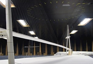
In the wide boundary-layer wind tunnel, we are able to test large-scale terrain models of the bridge surroundings. Our tests provide the bridge designers with an accurate description of the wind at the site when e.g. relevant meteorological records are not available or there is a need to correlate existing meteorological data from a distant station with the conditions at the construction site.
Based on digital maps of the site, the terrain surface is described using 3D CAD-software. From this software, milling files for FORCE Technology’s work shop’s automatic milling machine are generated. This permits a fast and precise model production.
The terrain model investigations are normally conducted for areas covering several kilometres. Typical model scales are 1:1000 to 1:2000.

Facility
In-house wind tunnel facility
Related services

Aerodynamic assesment of vessels
/Service
Aerodynamic assesment of vessels

Offshore aerodynamics
/Service
We perform wind tunnel studies for the offshore industry on numerous types of offshore structures.

Building aerodynamics
/Service
We test the wind environment surrounding a structure or site to ensure that it is optimised.