Knowledge about connector reliability can lead to more reliable products
The vast majority of electrical devices are equipped with one or more types of connector, which are known for often being crucial to the reliability of a product.
As a designer of electronic products, you may need to find out whether the connectors are the weak point in the design, and whether you have chosen the correct connection, which does not reduce the product’s reliability and robustness; or perhaps you need to ensure that the correct solution is implemented to address problems with electrical connectors in practical use. Likewise, designers or purchasers might sometimes need to research whether the cheaper connector really does fulfil requirements just as well as the alternative, so that a cost saving need not be at the expense of reliability.
In connection with the project “Reliable product development based on the Physics of Failure”, FORCE Technology has set out to find a simple method of answering these questions and gathering practical experience on the importance of materials, barrier layers, contact pressure and structural mechanical conditions.
Typical failure mechanisms related to connectors are triggered by mechanical, thermal or thermomechanical influences. Another group of failure mechanisms (corrosion) are triggered by moisture combined with an aggressive environment. This project has used the first group as its starting point, in order to expand upon the traditional HALT (Highly Accelerated Life Testing). HALT is an effective method of accelerating failure mechanisms related to temperature and vibration. Thus in connection with the project work has been done on targeting HALT to find weaknesses in connectors.
The HALT process is carried out as a classic thermal and mechanical HALT test. The connectors are subjected to an exploration of temperature limits, temperature cycling with ultra-high rates of change of tempeature of up to 60°/min., an exploration of vibration limits and a combination of vibration and temperature cycling.
There is focus on the connectors during the entire HALT process and a special measuring and monitoring method is used, so that “jitters” (ultra short interruptions), which are typically a sign that something is about to go wrong, can be detected.
- For each type of connector in the product, a suitable number of plug-in connectors are linked serially by soldering a wire from one connector to the next. It may be necessary to remove components from the PCB so they do not interfere with the test. At each end of the serial connection a cable to the measurement system is connected.
- The measurement system consists of a signal generator, a short circuit detector and a logging device.
- Once the first short interruption (down to 1 ns) has been detected, it is monitored and logged with reference to the time in the HALT test cycle.
- When the first occurrence of bounce is detected in a serial connection, the precise position is traced by further measurements in the serial connection.
- Once the connector type’s weak point has been ascertained, the physics behind the failure in the connector can be analysed in FORCE Technology’s failure analysis laboratory.
As the mechanical design has great influence on the reliability of the connector, it is important to test the connector in the setting where it will be used. It is important that all PCBs and components are in the product during the test. The PCB and components do not need to be operation. If needed, parts can be used that have suffered from production failure. All types of connectors in a product are tested simultaneously to find the weakest connection.
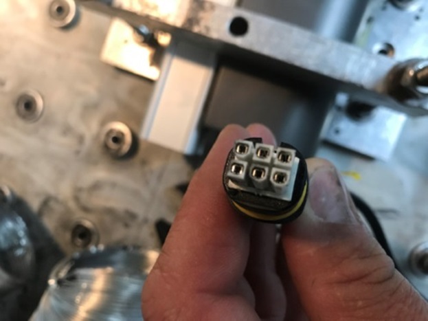
The method is used to study a variety of connector types, which are made available by Danish companies. The picture below shows one of the connectors with clear signs of wear powder after the HALT process.
Next, a failure analysis was carried out to examine more closely what has happened to the connectors. The failure analysis comprised optical microscopy and SEM-EDS ((Scanning Electron Microscopy – Energy Dispersive Spectroscopy).
The conclusion was that the primary failure mechanism was fretting corrosion. In addition, countless mating/unmating cycles had resulted in mechanical wear. Fretting corrosion occurs when there is a relative movement between electrical contacts with surfaces of base metals. The small wear particles oxidise, and the oxidised areas become larger and thicker on the contact surfaces. The basic function of the contacts is to ensure the transmission of electricity, but the oxidised particles are generally insulating. So a layer of oxide on the contact surfaces leads to poor contact and failure of the product. The lifetime of the contact is determined by the number of relative movements between the contact surfaces and the resistance of the oxide layer.
In the case of HALT both vibration and local differences in thermal expansion can lead to relative movement between the electrical contact surfaces. In this case the connectors were subjected to vibration, temperature changes and the effects of high temperatures, both on their own and in combination. During practical use, when the connectors are not necessarily being subjected to stress from their surroundings in the form of temperature changes, there is still a risk of relative movements between the contact surfaces due to self-heating and differences in the thermal expansion coefficients of the contact components.
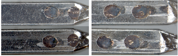
The pictures below show microscopic images of two different fingers. The one on the left is without an electrical connection and the one on the right with an electrical connection during HALT testing.
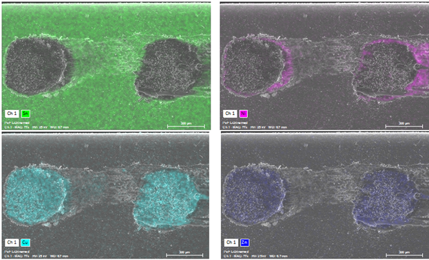
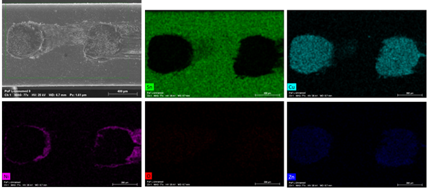
As can be seen from the pictures above and the corresponding EDS element mapping, copper and zinc are present, so we can conclude that the contact points are eroded down to the brass substrate due to fretting corrosion.


Compliance & Product Testing
What does the project show?
The article was published in
January 2018