Connector reliability testing ensures robustness
Connectors are notoriously considered the “bad boy” in the reliability class. Ensure correct robustness and reliability of the connectors in your product by means of connector reliability testing developed by FORCE Technology.
Most types of electrical equipment are equipped with one or more types of connectors. These connectors most likely have a significant influence on the reliability of your product.
As an electronics designer, you may be faced with the need to find out if the connectors are the weakest point of the design, or if the most suitable connectors have been selected in order not to reduce reliability and robustness significantly. Or you may be faced with the need to verify that the right solution has been implemented in order to mitigate electrical connector problems in the field.
Until now it has been difficult to ensure that the connector is not the limiting factor i.e. the weakest part. Therefore, FORCE Technology has developed a reliability test with the objective to assist you in obtaining the most suitable reliability and robustness level of the connectors in your product. However, it may also be a powerful tool for purchasing departments to benchmark different connectors in the search for cutting cost without sacrificing quality.
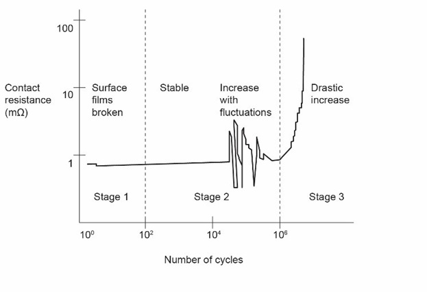
Most problems with connectors occur after a period of time in the marked. It can be very expensive to have many products on the market with incorrect connector reliability level.
The disconnection due to temperature cycling and vibration may lead to a built-up layer between the contact areas. Any type of short disconnection is called “jitter”.
The connectors are influenced by parameters like:
- Surface treatment
- Contact force
- Mechanical support
- Vibrations
- Humidity
- Corrosion environment
HALT (Highly Accelerated Life Testing) is an efficient way to accelerate the failure mechanism related to temperature and vibration.
Measurement and monitoring during HALT
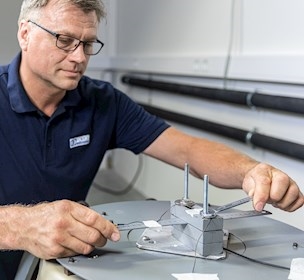
- For each type of connector in the product, a suitable amount of connections are connected in a serial row by soldering a wire from one connector to the next. It may be necessary to remove components on the PCB in order not to disturb the test. At each end of the serial row a wire is connected to the measurement system.
- The measurement system consists of a connector signal generator, detector circuit, and a logging mechanism.
- When the first short disconnection (down to 1 ns) is detected, it is monitored and logged with reference to the timing of the HALT test cycles.
- When the first jitter is monitored in a row of serial connected connections, the exact location must be investigated, by further measurement in the serial row.
- When the weak point of the connector type is found, the physics of failure in the connections may be analysed at FORCE Technology’s failure analysis facilities.
As the mechanical design has a very large influence on the connector reliability, it is important to test the connector in the enclosure in which they are used. It is important that all PCBs and components are in the product during test. The PCBs and components do not need to work. It is okay to use parts that have a failure from the production. All type of connectors in a product can be tested at the same time to find the weakest connection.

Compliance & Product Testing
Article