Advanced Vortex Induced Motions model tests
It has become common practice to carry out Vortex Induced Motions (VIM) tests for new platforms that may be susceptible to VIM.
Vortex shedding occurs on all blunt bodies subject to current. The shedding frequency is governed by the Strouhal Number and increases proportionally with the current velocity. The vortex shedding results in alternating cross-flow forces on the body.
Moored floating structures have natural frequencies in surge and sway dependent on the stiffness of the mooring system and the total mass of the structure including added mass. When these natural frequencies approach the shedding frequency, “lock on” may occur. The vortex shedding drives and becomes synchronised with transverse oscillations of the body with amplitudes of up to around half the characteristic body diameter.
FORCE Technology has extensive experience within VIM model testing of SPAR platforms, semisubmersible platforms and rigs.
For a floating platform, the horizontal mooring stiffness is determined by the horizontal component of the mooring line arrangement. A TLP is held in place only by vertical “mooring lines” or tendons under a pretension usually corresponding to 20-30% of the platform displacement.
Moored floating structures have natural frequencies in surge and sway dependent on the stiffness of the mooring system and the total mass of the structure including added mass. When these natural frequencies approach the shedding frequency, “lock on” may occur. The vortex shedding drives and becomes synchronised with transverse oscillations of the body with amplitudes of up to around half the characteristic body diameter.
FORCE Technology has extensive experience within VIM model testing of SPAR platforms, semisubmersible platforms and rigs.
Mooring system
Due to the limited water depth in our deep water towing tank, it is often necessary to truncate the mooring system into a system based on four horizontal mooring lines with helical springs.For a floating platform, the horizontal mooring stiffness is determined by the horizontal component of the mooring line arrangement. A TLP is held in place only by vertical “mooring lines” or tendons under a pretension usually corresponding to 20-30% of the platform displacement.
Mass and displacement
For floating platforms, the displacement and the mass are equivalent, but for TLPs, the tendon pretension pulls the model down, and the platform mass is less than the displacement. To model the dynamics correctly, the “displacement/mass ratio” must be modelled and hence the down force from tendons and risers. The horizontal mooring stiffness for TLPs is given by down force divided by tendon length. TLPs often operate on water depth of more than 1,000m. Assuming an appropriate model scale of e.g. 1:60, this requires a model tank water depth of minimum 16m. With only 5.35m water depth in our towing tank, we are unable to test scaled models with the correct length of the tendons.Air-bearing push down system
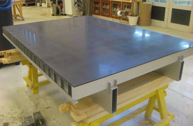
Instead of pulling the model down with tendons, it is possible to push the model down, but this requires a system where the model is completely free to move in the horizontal plane. For this purpose, an air-bearing push-down system was designed.The system consists of a light, stiff aluminium structure with a perfectly flat and smooth underside, the “air-bearing plate”, fixed under the carriage. On a rotatable platform resting on the top of the TLP model, four upward-facing air lubricated self-levelling pads are mounted pushing against the air-bearing plate. The system restricts motions in heave, pitch and roll, while allowing surge, sway and yaw motions with very little damping. The TLP model is de-ballasted to obtain the correct push down force corresponding to the scaled tendon pretension plus down pull from risers.
To ensure proper performance of the air bearings, considerable work effort was spent on diamond lapping/polishing of the air-bearing plate.
The air-bearing system was tested in air prior to the tank tests, and the damping of the air-bearing pads alone was found to correspond to less than 0.2% of critical damping.
Optional damping
If damping from tendons, risers etc. is required to be modelled, FORCE Technology can adapt a dedicated damping system based upon client-specified levels of damping in the sway motion.Measurements
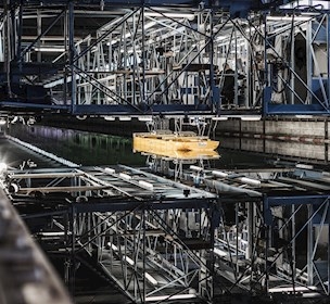
Under each air pad, a force gauge is mounted to measure the vertical force. The measurements are made to ensure that the push down force is correct, that the load is evenly distributed on the pads and to document the dynamic roll and pitch moments during the VIM test.Motions in surge, sway and yaw are measured by our standard optical tracking system. The model is kept in position by our standard mooring system consisting of four horizontal mooring lines with the correct model-scale stiffness (corresponding to the full-scale TLP tendon system), and each line is attached to a gauge on the carriage measuring the transverse and longitudinal forces. The system has already been used successfully for client projects and will be used for all future TLP projects of this nature.

Jesper Grundsøe
Sales manager, CFD, Hydro- and aerodynamics, Hydro- and aerodynamics
T. +45 30 28 31 08
Contact Jesper
Facility
Towing tanks
Facilities letting our customers their test ships and offshore structures under extreme conditions.