How stressors affect the lifetime of electronics
Lifetime of electronics is affected by well-known stressors, such as temperature, humidity, and vibrations.
Electrical stressors in the electrical Mission profile
Lifetime of electronics is affected by well-known stressors, such as temperature, humidity, and vibrations. The lifetime is also shortened by electrical effects, such as large pulse currents in components, and - in the worst-case scenario - explosion or combustion. Electrical stressors belong to the electrical usage environments; apart from transients, they may also consist of disturbances in the power supply. Both stressors are a part of the electrical “mission profile” that a product experiences over the course of its life. The data for the mission profile might, for example, be retrieved from comprehensive data collected by Danish Energy, with transients from a total of 70 years of observation documented since 2009. Some products go through their entire lives with very stable power supply quality, while others experience transients, distorted waveforms, and possibly thousands of on/off events or power failures.
The acceleration model and lifetime calculation
Reliability and lifetime testing are very costly. Lifetime estimation using computer models is progressing, and these analyses can be a useful tool in the future, such as when developing power electronics.
AAU (Aalborg University), working together with the industry in the CORPE co-operative project, has developed an estimation tool for state-of-the-art mathematical modelling of electrical and thermal conditions. This tool can be used to evaluate the most significant stressors for wear and tear on electronics. The tool is used on active components, such as IGBTs and MOSFETs, but is currently being extended to include also critical passive components, such as fuses and metal oxide varistors (MOVs). The effects of such parameters as temperature, voltage, and humidity are used as a mission profile, and models for these are under ongoing development.
Lifetime estimation for components in power electronics is performed based on acceleration models, which describe the impact of each stressor condition and the aggregate stress from all of them combined. These acceleration models are derived from real-world lifetime testing, which means they are reasonably precise for a given component construction and the associated physical failure mechanism.
Co-operation with specific cases
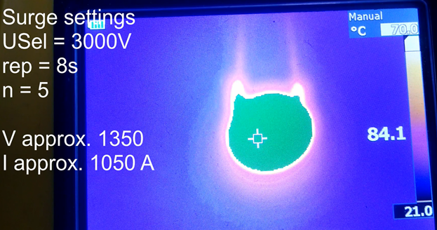
Throughout a variety of activities, AAU and FORCE Technology have worked with analyses of specific cases involving electrical stressors. The process of creating an acceleration model for a varistor is carried out using transients as the stressor.
Long usage periods are not as relevant in the case of a varistor. The number of high-amplitude events (transients) to which the varistor is subjected is more relevant. These short, high-power, high-temperature events are the key factor in varistor breakdown. A stable nominal voltage has an insignificant effect. Thus, the acceleration model needs to be based on a mission profile consisting of events.
A practical test is used to see how many electrical impulses are required to cause a breakdown in a varistor at a variety of temperatures and current amplitudes. A mathematical acceleration model is created based on the test. Using the acceleration model, a lifespan in terms of the number of electrical impulses can be calculated for different currents and temperatures.
New stressors, known challenges
Our experience with the electric stressor lifetime module has shown that they come with the same challenges associated with classic thermal and mechanical stressors, such as:
- The acceleration curve may be very steep, such that virtually no wear occurs at low current amplitudes, while destruction (combustion/explosion, and thus an overstress failure mechanism) occurs at an amplitude only slightly greater.
- Generally, an acceleration model is only applicable to a single failure mechanism.
- Many series of input data - and thus extensive testing - are required to establish acceleration models for temperature, electrical impulses, and supply voltage.
A case involving transmission line aspects
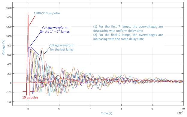
The figure 1a & 1b below show the variation present under the influence of a transient. A transient of 1500 V with a duration of 10 μs is applied to a series of street lights installed with overhead power lines. The coloured curves show the voltage across each of the 9 lights, spaced 54 m apart, each with its own varistor. The transient is applied at one end of the series, so we might expect the transient amplitude to gradually decay as the transient travels down the line. However, the model shows that the final two lights are subjected to a higher amplitude due to the reflection from the "unterminated" wiring. This must be taken into account in determining the lifetime of the street lights. Simple estimations also show, that if the transient amplitude is brought above 2 kV, a fuse (slow-blow, 3.15 A) in each driver will melt and disconnect the light. The fuse cannot be replaced as the lamp driver electronics are potted, so the light cannot function until a new driver is installed.
This article was published in SPM Magazine, August 2018.

Compliance & Product Testing
Facility
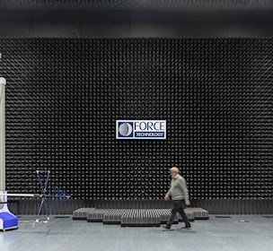
Explore our EMC testing facilities
Article
How to calculate the lifetime of an electronic product

Sustainable products and materials
We need to consume resources more wisely and use products in smarter ways, make them last longer, and find better ways to reuse or recycle them.