3D bridge model tests
Bridge model tests are an essential part of the design process. Our aerodynamic tests can help reveal possible adjustments that are necessary in order to build a safe and efficient bridge.
Wind testing of a landmark footbridge in Hong Kong
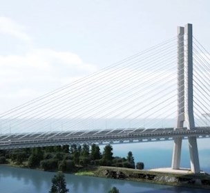
The Government of the Hong Kong SAR (Civil Engineering and Development Department, New Territories East Development Office) commissioned us to test the effects of wind on a new long-span footbridge crossing the Eastern Channel at Tseung Kwan O in Hong Kong.
The iconic structure consists of a deck girder curved in plan in a waveform, together with an arch rib crossing diagonally above the girder. The girder is supported by the arch rib through an asymmetrical array of steel plated hangers. The designer is AECOM Asia Co. Ltd.
“A landmark bridge like this is a very large investment, which is why it is important to be sure that the bridge can withstand all types of wind loads before building it,” says Søren Vestergaard Larsen, Team Leader of the department for Hydro- and Aerodynamics at FORCE Technology.
The process of creating a replica
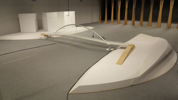
In order to perform the tests, we used our software to create a 3D aeroelastic model of the bridge at a 1:40 scale. The model was built according to drawings and data provided to us by the designer.
In this particular case, we found that it was difficult to design and produce an aeroelastic model of the bridge using the traditional spine technique where aluminum spines are used to simulate the scaled bending stiffness of the bridge’s structural elements. For this particular bridge, the axial stiffness of the arch and tie was difficult to achieve through the standard spine technique.
“Normally we use the spine to achieve the correct bending stiffness of the bridge’s structural elements, then we would add cladding elements on top of the spine to obtain the correct shape and geometry, and finally we would add some mass to obtain the correct weight of the bridge. In this case, we found that it was impossible to model the bridge correctly using this method. This is why we chose to use a polyurethane material in order to model geometry as well as stiffness. This material meets the exact characteristics in bending and axial stiffness when given an appropriate thickness. Afterwards we added brass loads to achieve the correct mass of the bridge,” Søren explains.
At first, part-models representing selected characteristics of the aeroelastic model were tested, to assist in the full bridge model design and manufacture, and to examine if any adjustments were necessary, then the full bridge model was tested in one of our wind tunnels.
Putting the bridge to the test
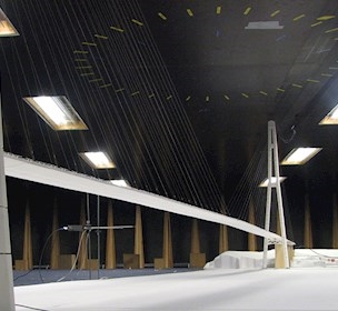
We performed the wind tests in our 7.5m wide Boundary-layer wind tunnel. The effects of smooth flow and turbulence were tested. We also tested if possible future surrounding skyscrapers would create additional turbulence by creating foam models of the potential surrounding buildings. In all, eight possible wind directions for each of the three different types of wind exposure were tested.
Simulating realistic turbulence for reliable results
In order to simulate turbulence, we use different tools. Examples of this are a carpet on the floor of the wind tunnel and triangular tapered spires placed in front of the model to create turbulent eddies. This way we were able to create a realistic wind exposure. The tests documented that the bridge would have no undesirable vibrations when exposed to the different types of wind.
“When the tests are concluded, we give the designer data measured from instrumented stations on the aeroelastic bridge model, showing the buffeting response of the bridge when exposed to increasing wind speeds. In this case, the designer can use these results to confirm that the structure is adequate to accommodate the wind loads. We do, however, have projects where we find that adjustments have to be made in order for the bridge to be safe and efficient”, concludes Søren.

Case
Test of new bridge cabel concept
Facility