Aeroelastic analyses of the Agin and Nissibi Bridges: Wind tunnel tests in Turkey
FORCE Technology has performed extensive wind tunnel tests for two new cable-stayed bridges in Turkey.
The tests comprised aeroelastic full-bridge model tests and in one case also section model tests of the bridge deck.
The investigations were performed for MEGA YAPI Construction & Trade Co Ltd and Turkish General Directorate of Highways Authority, Turkey.
Agin Bridge
The Agin Bridge in Turkey is a 520m long cable-stayed bridge with a main span of 280m. The bridge has two steel column pylons with a height of about 86m. The steel column pylons will be erected on existing concrete piers. The bridge girder cross section for the main span is a closed trapezoidal box, and the total width of the deck is 13m. The deck is supported by stay cables in a central plane.
Initially, the aerodynamic properties of the bridge deck were investigated through deck section model tests. These tests established the fundamental aerodynamic characteristics of the deck section, i.e., force coefficients, flutter limit, vortex-shedding characteristics and aerodynamic flutter derivatives. Elaborate full-bridge model tests were used to establish the wind-induced forces, moments and displacements of the entire structure. These are important parameters for the designers in order to verify aerodynamic stability and wind loading of the structure. The full-bridge model tests were conducted for both the in-service stage and the final construction stage just prior to closure at mid-span where the bridge deck is fully cantilevered. And for both configurations, the tests documented the aerodynamic stability of the structure.
Nissibi Bridge
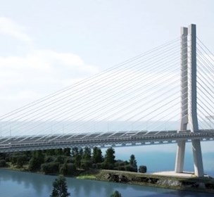
The Nissibi Bridge in Turkey is a 610m long cable-stayed bridge with a 400m main span. The bridge deck in the main span is an approximately 23m wide trapezoidal steel deck. The deck is supported by double fan-shaped cable planes and inverted Y-shaped concrete pylons. Full-bridge aeroelastic investigations similar to those conducted for the Agin Bridge were performed in order to establish the bridge’s aerodynamic behaviour and document its aerodynamic stability.
Aeroelastic models
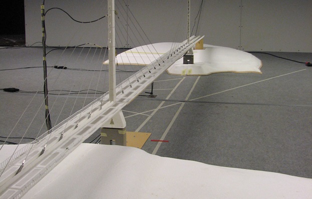
Both structures were represented by 1:100-scale aeroelastic models. Aeroelastic models not only represent the external geometry of the bridge in detail, but also model the mass distribution of the deck, pylons and cables, the mass moment of inertia of the deck, the stiffness of the deck, cables and pylons, and the drag characteristics of the cables and deck. The resulting model response to wind action in the wind tunnel closely corresponds to the response of the prototype structure to natural wind.
Aeroelastic models may be tested to examine susceptibility to vortex-shedding-induced oscillations, buffeting response to turbulent wind, lateral and vertical accelerations and deflections, bending moments of the deck at the pylon, pylon base-bending moments, pylon deflections and the response of the bridge to wind from yaw angles. In short, aeroelastic model tests give a complete description of the bridge response to wind action.
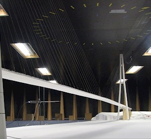
Five wind tunnels
FORCE Technology operates five wind tunnels. The aeroelastic full-bridge model tests described above were conducted in our wind tunnel 4. This wind tunnel is 7.5m wide and 1.7m high and has a maximum speed of 12m/s. The tunnel has a working section sufficiently long to establish a simulated atmospheric boundary layer. This makes this facility well suited to study the aerodynamic behaviour of civil engineering structures such as buildings and cable-supported bridges.
Søren Vestergaard Larsen
Case
Test of new bridge cabel concept
Facility