Accelerated lifetime tests based on the Physics of Failure
Danish companies need methods to find out how long their products will last, so that they know what they can guarantee as well as what that guarantee will end up costing.
Danish companies are experiencing an increased need to analyse, verify and document the lifetime of newly developed or existing products. They need methods to find out how long their products will last, so that they know what they can guarantee as well as what that guarantee will end up costing. For marketing purposes there may also be a need to know how long the company’s products will last compared to its competitors’. Therefore, more and more companies need to design and implement an accelerated lifetime test.
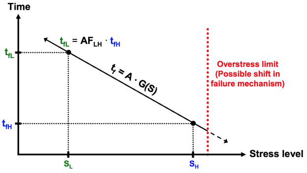
An accelerated lifetime test is basically a way of fast forwarding time so that we do not have to wait 20 years to find out whether a product can actually last 20 years in the real world. In a nutshell, during testing the product is subjected to a higher stress level so failures appear faster than they would in reality, making it then possible to calculate the time it would take for that failure to appear at the lower, actual stress level. See Figure 1.
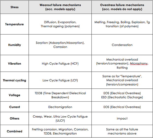
Note that it is only wearout mechanisms that can be exposed with an accelerated lifetime test. Overstress failure is not time-dependent in a way that can be described with the help of normally-used acceleration models, but depends instead on brief stress levels that exceed a threshold value and lead to sudden failure. This is illustrated in the two columns in table 1.
What is an accelerated lifetime test?
An accelerated lifetime test can be carried out either as a classic accelerated lifetime test, where a large number of samples of the new product are subjected to test stressors determined beforehand until a period of time has passed corresponding to the desired lifetime, or the product fails.
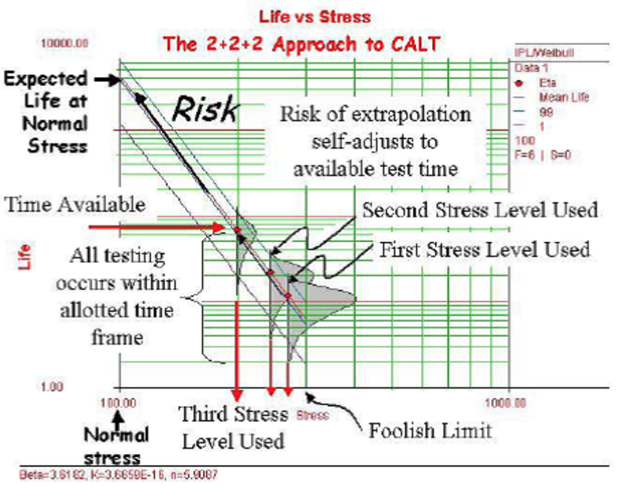
The accelerated lifetime test can also be carried out as a CALT (Calibrated Accelerated Life Test). Firstly, two samples of the product are subjected to test stress that is close to the level where the products will break immediately (foolish limit), after which a further two samples are subjected to stress at a level that is slightly lower than the first level. Once you know the time to failure for the 2 x 2 samples at the two levels, you can then calculate (or calibrate) the level for the test stress which the last two samples must be subjected to and thus get them to fail within the time that is available in the development project. See Figure 2.
The lifetime test targets the product’s failure mechanisms
Before you charge headlong into performing one of these types of accelerated lifetime tests, it is necessary to find out which type of test stress is relevant for the product in question. This is where knowledge about the Physics of Failure or the product’s failure mechanisms comes into play, because the accelerated lifetime test must be targeted at the failure mechanisms in the product being studied. This is easier said than done, especially if it is concerned with complex products with many different components and thus many different failure mechanisms.
Imagine a film capacitor in an electronic control unit that has a number of different failure mechanisms which can all lead to changes in capacity and/or in ESR (the equivalent series resistance), resulting in the capacitor stopping working as intended. Examples of failure mechanisms could be break down of the metallisation layer in connection with self-healing, corrosion of the metallisation layer, corona effect resulting in evaporation of the metallisation layer, electrochemical corrosion or a change in the polymer’s properties due to the effect of temperature.
The electronic control unit consists of many other components however, each with their own failure mechanisms. There may be connectors that fail due to a poor contact – either briefly or permanently. The failure mechanism could be fretting caused by countless large temperature changes or vibrations.
The control unit may also consist of semiconductors, which change characteristics due to a diffusion of the semiconductor materials into each other caused by the effects of temperatures and thus lead to a failure in function of the control unit. Or perhaps there are heavy components that, with time, break off due to fatigue in the leads, if the control unit is mounted on a vibrating environment.
No single accelerated lifetime test can address all the potential failure mechanisms in complex products. The challenge is therefore to find the failure mechanism that is most relevant to test for.
The solution is to assess which failure mechanisms are dominant or most relevant for the individual product. Inspiration may be drawn from failures occurring in similar products on the market, as well as technical literature, exchange of experiences with experts in the same field e.g. in experience exchange groups (also known as Erfa-groups), help from specialists or the results of HALT tests (Highly Accelerated Limit Test). In connection with the project “Reliable product development based on the Physics of Failure” FORCE Technology is currently establishing a knowledge bank for the Physics of Failure in electronic and electromechanical products.
The dominating failure mechanism for the product determines which test stress is relevant for the accelerated lifetime test. Examples of common wearout and overstress failure mechanisms from the SPM-179 report can be seen in table 1.
Selecting the correct acceleration model
Each wearout failure mechanism has its own acceleration model:
- Temperature-related and chemically-related failure mechanisms can be described using Arrhenius’s acceleration model
- Vibration-related failure mechanisms and other “mechanical” failure mechanisms can be described using “inverse power law”
- Humidity-related failure mechanisms can be described using the Peck, Hallberg-Peck or Lawson models
For each model, the parameters are adapted to the actual situation.
How is the effect of stress quantified?
The acceleration models describe, as previously mentioned, the connection between a specific stress and the time to failure. The acceleration model is used to calculate the time it will take to failure in reality based on the time to failure during the test, when you know the stress load in reality.
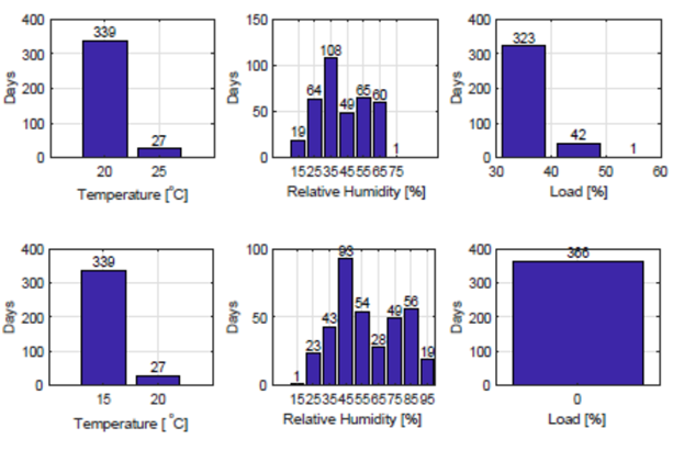
The next challenge is to quantify the use load. Many products are used in many different situations in many different places in the world. One important tool to describe use load and to quantify them is “mission profiling”, where the types of load, levels of load and the frequency of these are described in a systematic manner. Figure 3 shows a simple “mission profile” for the control unit in the previous example in an industrial application (top) and during storage (bottom). Both applications take place in Denmark.
When the accelerated lifetime test has been completed, the results are analysed to work out the lifetime for the product. Statistical tools are useful in this connection.
It is also recommended that the tested products are analysed partly to find out whether the products have degraded beyond that which can be registered by monitoring the function during the test, and partly to examine whether the failure mechanism(s) found correspond to those which were expected. This typically begins with a visual inspection both inside and out. Depending on need this can be followed up with an X-ray analysis, microsectioning, analysis of deposits, contamination or corrosion products etc.
The procedure for an accelerated lifetime test
Knowledge about the Physics of Failure and the failure mechanisms which are dominant in the product that is examined is thus crucial in planning and carrying out an accelerated lifetime test.
The following procedure is suggested for an accelerated lifetime test:
- Identify relevant wearout failures and the related failure mechanisms
- Decide which failure mechanisms the accelerated lifetime test should address
- Define use and function loads (“mission profile”)
- Determine threshold values for test stresses based on material and component data
- Make an estimate of the potential acceleration by calculating the acceleration factor based on the acceleration model
- Carry out the accelerated lifetime test
- Carry out a (failure) analysis of the tested samples of the product
- Analyse the test data and calculate the lifetime for the product
Contact
For more information about the Physics of Failure and accelerated lifetime testing, contact Senior Specialist Susanne Otto, FORCE Technology.Article from Aktuel Elektronik, April 2018

Compliance & Product Testing

Facility
Reverberation chamber for EMC testing your product

Facility
Mechanical testing – vibra-tion, shock, transport etc.

Facility