Assured capacity of thermal energy storage using CFD
Guaranteed thermal capacity is possible by using CFD in the design of your thermal energy storage. Obtain an efficient and cost-effective solution with undisturbed thermal layers during operation.
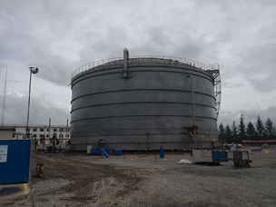
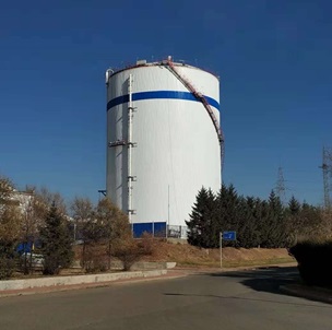
Storing Energy: From waste to resource with thermal energy storage
Storing surplus heat or chilled water from industrial processes is a challenge that when solved, creates economic benefits both for industrial process plants, CHP plants, hospitals, pharmaceuticals and more. Moreover, the environmental benefits for society due to reduced over-production and minimized waste is substantial. This is where thermal energy storage, also known as heat storage tanks, makes a difference.
For industrial processes, thermal energy storage allows saving waste energy, for later reintroduction into the system when needed. The storage reduces the need for auxiliary equipment to re-generate energy that has already been acquired at an earlier stage. For combined heat and power plants, thermal storage allows closing the time-gap between production and use of district heating and electricity. In pharmaceutical or hospital practice, chilled or ‘cold’ water tanks are used to store cooling water for production and cooling purposes. A storage tank ensures that energy generated at specific hours of the day, can be stored and used later when the demand rises.
Meeting the designed capacity of the thermal energy storage
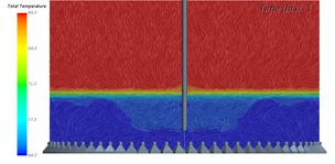
Proper functioning of a stratified water thermal energy storage is directly related to its ability to meet the designed thermal capacity, as well as to preserve high temperatures inside the tank.
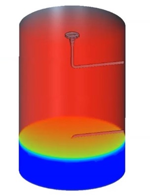
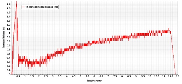
To control the latter, special attention must be paid to the thermal layer, which is the layer that naturally separates cold water at the tank’s bottom from hot water at the top. A good design implies a thin thermal layer, meaning that there is only little mixing between hot and cold water.
How to minimise the thermal layer
Hot and cold water enters and leaves the tank during charging and discharging. This process induces turbulence and mixing inside the tank, disturbing the thermal layer thus increasing its thickness. Such disturbance creates permanent thermal losses and reduced tank capacity, which cannot be recovered. This leads to continuous economic losses for the end user.
In order to preserve an undisturbed thermal layer, reduce thermal losses, and maintain a high thermal capacity, water must enter and leave the tank through diffusers that create as little turbulence and mixing as possible.
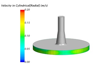
Using Computational Fluid Dynamics (CFD) to guarantee high thermal capacity and minimum thermal layer
Through advanced CFD simulations, we design and validate thermal energy storage systems that maximise efficiency, reduce energy loss, and ensure long-term reliability. Our services cover design and optimisation of internal piping systems and diffusers, ensuring optimal functioning from a flow and mechanical perspective.
Our CFD design procedure ensures:
- high thermal capacity
- thin thermal layer
- minimum thermal losses by reducing turbulence, mixing effects and optimal design of flow in pipes
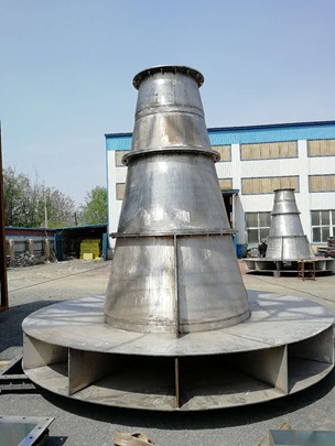
- reduction of diffusers size and weight compared to conventional design methods
- design flexibility, upon feedback from construction teams.
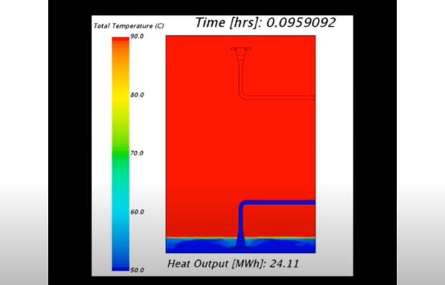
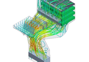
Through CFD, we are able to predict flow behaviour inside the tank. This is crucial for its proper functioning. Such detailed overview provides valuable information that would otherwise only be available once the thermal energy storage is constructed and tested. By leveraging CFD simulations, we eliminate uncertainty in thermal energy storage design. Our process ensures optimal performance, cost savings, and a data-driven approach.

Webinar-on-demand
Energy: Optimisation of Flue Gas Cleaning Solutions with CFD
Related services
Combustion simulation and consultancy using CFD
Consultancy on design and optimisation for flow solutions ensuring optimum performance of the plant.
Design and validation of flue gas cleaning systems
CFD design and assessment to assert environmental regulation compliance.
Ventilation systems and CFD
Design and validation of efficient ventilation systems using CFD