The Bulderbaan is a unique air calibration facility for all types of air and flow meters
At one of the largest air calibration facilities in the world, we conduct first-time verification, control and recalibration of volume, mass, and dP meters using atmospheric air.
Meets your air calibration needs and provides accurate results
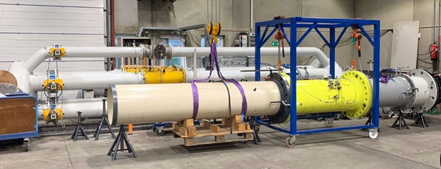
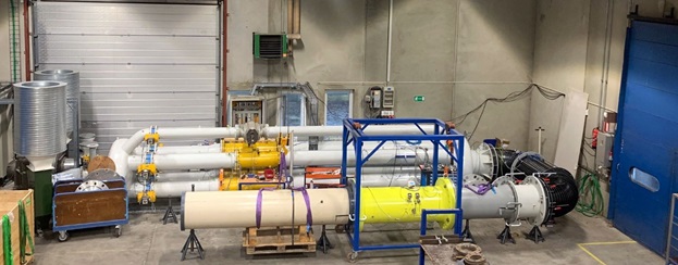
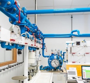
Fourteen metres long and 1,8 metres high, our airflow calibration facility is one of few to offer a flow range capacity from 65 (Q-min) to 25000 m3/h (Q-max).
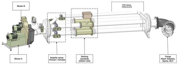
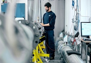
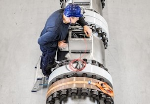
The air facility consists of five parallel reference lines and a measuring line in series where the meter under test (MUT) is located. The airflow facility operates according to the suction principle under atmospheric conditions. Two Revolution Per Minute (RPM)-controlled centrifugal blowers draw air from the calibration room through the meter during testing and then through the reference strings containing the working standards further downstream.
Flow distribution:
- (BU201) Blower A: Supplies WS201, WS202, and WS203 with air flow
- (BU202) Blower B: Supplies WS204, and WS205 with air flow
Calibration of all types of air and gaseous flow meters
The air calibration facility can handle all flow meters for measuring air and other gasses, including USM, turbine meters, swirl meters and coriolis meters up to 50" in diameter.
Air calibration specialists at your service
As an impartial and independent calibration service provider, we maintain and develop a technological infrastructure of unique facilities, technologies, and competencies for society and business.
Contact us to find out what we can do for you.
Look around the Bulderbaan airflow calibration facility
