
By Lonna Dickenson, Emerson
Importance of managing fiscal risk in large volume gas custody transfer.
Gas custody transfer refers to financial transactions in which ownership of natural gas – typically methane – is transferred from one operator to another. This involves the transfer of significant quantities of gas, with money exchanged based on accurate measurement.
Due to the high value of the gas being transferred, custody transfer demands the highest levels of flow meter accuracy, reliability, and measurement availability. As the volume increases, so do the stakes. For example, even a small error of 0.25% could equate to financial risk of ~$480,000 per year on 3 million standard cubic meters per day at $5.00 per million Btu (based on historical EU natural gas prices). Measurement errors increase financial exposure and can lead to costly litigation and settlements.
Industry best practice for setting gas measurement uncertainty
Given the large economic risks, pipeline companies and operators often set uncertainty budgets to mitigate financial exposure.
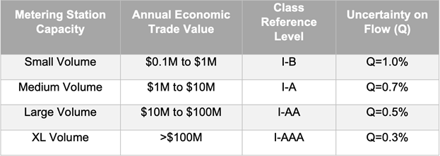
Their guidelines, shown in Figure 1, recommend uncertainty limits based on annual economic trading value.
For an economic trading value up to $100M, the recommended uncertainty limit is 0.5% of the flow. This helps keep the customer’s financial exposure around half a million dollars annually at large volume stations. For system uncertainty budgets, the American Gas Association (AGA) suggests a limit of 1.0%, or about $1M in overall uncertainty for large metering stations.
These recommended budgets are based on balancing the cost of advanced measurement solutions with the financial implications of uncertainty, while also accounting for current measurement technology capabilities, prices, and uncertainties.
For smaller volumes with lower annual economic risk, less robust technologies such as ultrasonic meters with fewer paths and no redundancy may be acceptable. However, in large volume gas custody transfer applications, the high cost of uncertainty demands that state-of-the-art technologies evolve to meet stricter uncertainty budgets.
Three prevailing large volume gas measurement technologies
Most pipeline operators aim for an operational measurement uncertainty of less than 0.3%, but achieving this is challenging, even with custody transfer-rated meters. Meeting this threshold often requires addressing limitations in piping design and meter technology. Even then, this uncertainty is typically only achieved when the highest accuracy flow meters operate in ideal conditions.
The accuracy of individual calibrated meters (turbine and ultrasonic) and uncalibrated orifice fittings ranges from 0.1% to 0.25%. However, installation uncertainty must also be considered, with a typical uncertainty allowance of +/-0.167%, the lowest accredited by international metrology standards (achievable only with best-in-class custody transfer meters).
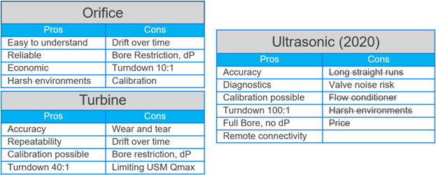
There are three dominant technologies used for large-volume gas custody transfer:
- Differential pressure (DP) meters: First introduced in the 1930s, DP meters are available in various sizes and excel in harsh environments. The orifice fitting, a type of DP meter, was the most common type used for custody transfer until the 1980s, when turbine meters gained acceptance for custody transfer, particularly in cleaner downstream environments like gas pipelines.
- Turbine meters: Known for their high accuracy, repeatability, and broad turndown ratio (the range of flow velocities they can measure accurately), turbine meters are flexible for operational changes such as flow rate fluctuations. These meters are now widely used for gas custody transfer.
- Ultrasonic flow meters: Though ultrasonic measurement technology existed since the 1960s, it was not widely accepted for gas custody transfer until the late 1990s, with the publication of AGA 9. This report provided clear metrological guidelines, leading to global adoption. Early ultrasonic meters faced criticism due to poor designs and misunderstanding of the technology. However, advancements in path configurations, processing speed, digital signal processing (DSP), and software have significantly improved performance, diagnostics, and usability.
The rise and evolution of ultrasonic flow meters
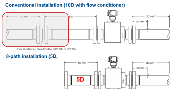
Ultrasonic meters continue to evolve, with increased accuracy and reduced sensitivity to flow profile effects, allowing more compact installations and eliminating the need for flow conditioning. Enhanced diagnostic paths and predictive maintenance features are among the latest innovations. However, challenges remain, such as valve noise interference. Advances in noise isolation, DSP, higher frequency sensors, and filtering techniques mitigate this risk, resulting in more robust measurements.
Additionally, ultrasonic meter designs have become more durable, capable of withstanding harsh environments. These improvements, along with decreasing prices, have accelerated the adoption of ultrasonic meters, driving the industry to reevaluate older measurement standards.
Minimising the effect of process disturbances on operational uncertainty
Even with the most advanced technology, operational uncertainty is often influenced by process disturbances that are not accounted for in the uncertainty allowance. DNV GL’s research revealed that 75% of metering errors are process-related, with only 25% stemming from the meter itself. Disturbances such as pulsations, valve noise, blockages, and contaminants can significantly impact measurement accuracy.
Meter drift over time is another concern. While sophisticated diagnostics help detect drift, many countries still use calendar-based recalibration schedules. Taking a meter out of service for recalibration is costly, requiring bypasses, spare meters, contractors, and downtime.
To minimize operational uncertainty in high-pressure metering stations, some European countries and North American transmission operators have adopted the best practice of using two meters in series. The second meter serves as a check to verify the primary custody transfer measurement. Initially, this practice involved using turbine and orifice meters or turbine meters with ultrasonic meters.
In 2013, as European Union pipeline infrastructure evolved to enhance security of supply, two different ultrasonic meters were accepted for bidirectional installations, with this approach extending to unidirectional installations.
In 2015, the German metrology institute (PTB) legalised the use of two ultrasonic meters in series, provided they had different path configurations. This approach allows for extended recalibration cycles if the two meters align. Other countries and operators soon followed suit, but the question remains: Is there more to consider?
The problem of common mode error
The original rationale for using two meters in series was to reduce common mode error - when two meters react similarly to disturbances, masking underlying issues. However, dissimilar meters can still exhibit common mode error if they respond similarly to certain process conditions.
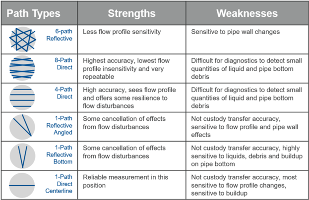
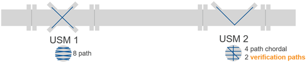
For instance, both orifice meters and ultrasonic meters can overread in the presence of liquid or buildup. If two ultrasonic meters share similar path configurations, common mode error can still occur. To address this, combining different path types (direct and reflective) in a meter can enhance diagnostics and reduce the risk of common mode error. Reflective paths are sensitive to pipe wall effects and can detect issues like buildup or contamination early.
New test qualification for limiting operational uncertainty
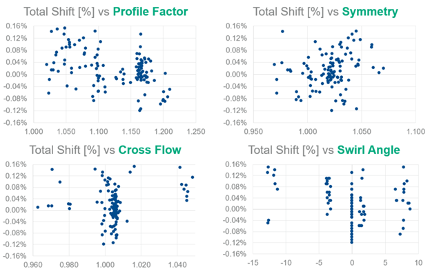
While traditional metrology standards focus on calibration and installation effects, they fail to account for real-world operating conditions. DNV GL’s new test qualification addresses common process conditions that impact operational uncertainty. These conditions, found at field sites globally, were used to design test criteria that better reflect the uncertainty seen in the field.
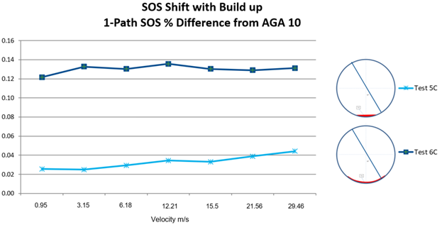
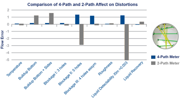
For example, reflective and direct path meters show opposite flow error biases, helping to detect process disturbances early. In contrast, liquid or buildup contamination requires the comparison of speed of sound (SOS) between different meter types and paths to identify issues.
An ideal combination for minimizing operational uncertainty
With the evolution of technology, ultrasonic meters now offer more paths, such as 8-path meters. These advanced meters improve measurement accuracy, maintain high performance despite upstream disturbances, and reduce the need for lengthy upstream piping or flow conditioning.
For example, Emerson’s Daniel 3418 meter, combined with the Daniel 3416, offers a robust combination for maximum accuracy, repeatability, and process intelligence. These meters provide high reliability even under challenging conditions, offering operators an optimal solution to minimize operational uncertainty.
Looking ahead: What's next?
The rapid evolution of ultrasonic technology has expanded its use beyond clean, dry gas environments. Ultrasonic meters are now widely accepted in applications like wet gas, corrosive environments, biogas, coal bed methane, LNG, and more.
The development of condition-based monitoring systems, machine learning, and artificial intelligence is poised to further enhance the capabilities of ultrasonic meters. With increased investment in IoT infrastructure, operators are now able to move diagnostic data to the cloud, unlocking new potential for process management, system uncertainty reduction, and predictive maintenance.
As these technologies continue to mature, it’s clear that ultrasonic metering solutions are not only advancing in robustness but also intelligence. With this progress, they may soon exceed the long-term repeatability of turbine meters, marking a new era in gas custody transfer technology.
Interested in this topic? Sign up to receive news and articles about gas flow calibration or read more about calibration here.
