Uncertainty explained: How is a calibration result reached?
In order to understand uncertainty calculations, it is necessary to know how a calibration result is reached.
By doing that, we can better identify the parameters which can have a possible influence on a calibration result, and this becomes vital in order to create an uncertainty budget.
Read along, while we explore the importance of specific factors and measurements from an uncertainty perspective.
> Uncertainty explained: Understanding an uncertainty budget.
The technical part: How do calibration laboratories reach a calibration result?
When calculating uncertainty, one starts with a model equation. So, we start by asking the question: How do calibration laboratories reach a calibration result? That is, how do you calculate the error of a meter under test (MUT)?
To do this, we take a top down approach and start with the basics of how to calculate the calibration result or error of a MUT. A calibration result can be calculated based on flow or volume with the following equation:
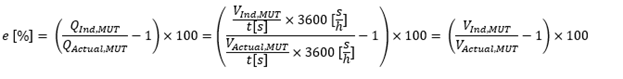
In the following calculations, we assume an accurate enough signal collection system, that the signal collection starts and stops at the same time for both the Meter Under Test (MUT) and the working standards (WS) used to calibrate the MUT. Thus, subsequent calculations will all be done based on volume.
Here, laboratories normally use reference meters, also called working standards or (WS). These WS have themselves been calibrated and are set up in series with the MUT. By using these meters, and continuously collecting data from the WS, calibration laboratories know the gas flow through the WS at all times, although of course with an uncertainty, but we will come back to that later.
But to generate flow in a system, a pressure difference is generated and there might also be a temperature difference between the WS and MUT, so knowing the gas flow rate at the WS’s is not enough. This is where the “ideal” gas law comes in. However, as we are not working with ideal gasses, we add the compressibility factor to the ideal gas law equation.

And if there is no pressure leakage in or out, and the amount of gas stays the same between the WS and the MUT, we should get the same mass flow trough the WS and the MUT. Expressed in another way, we should have the same amount of mol (n) through the meter under test and the working standard.
So, for calibration laboratories this means that if there are two positions 1 and 2, where gas flows through both positions and there is no loss or gain of gas between the positions, then the same amount of mol flows through the two positions.

Using this condition, we can now isolate V1 on one side of the equation and instead of calling it position 1 and 2, we say that these two positions are the positions of the WS and the MUT in the calibration loop. Using this, we can now isolate V1=VMUT on one side of the equation. Since both sides of the equation divide by the constant R, it falls out and we get:

Since the WS is itself a calibrated meter, we can obtain a VActual, MUT that is traceable to the WS if we correct for the error of the WS, based on its calibration. So, we get:

We now have all the elements that are used to calculate the error of a MUT in a calibration, so the model equation (equation 1) can now be expanded upon so:
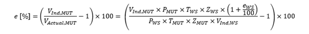
Using this expanded form of the model equation, we have all the factors needed to calculate uncertainty in a calibration.
Want to know more about uncertainty and calibration results?
- We are always open for discussions - contact us.
- Sign up to receive news and articles about gas flow calibration
- Read more: Uncertainty explained - Class Half meters
- Learn more about Calibration here.
Symbols
The equations used in this article use symbols that are based on what is normally used in international standards and documents.
| Symbol | Description |
|---|---|
| MUT | Meter Under Test, also sometimes called DUT (Device Under Test), is the meter/device that is being calibrated. |
| WS | Working Standards are reference meters, used to calibrate a MUT. |
| P | Pressure, where PWS is pressure at the WS and PMUT is pressure at the MUT. Pressure is always measured in absolute pressure. |
| T | Temperature, where TWS is temperature at the WS and TMUT is temperature at the MUT. Temperature is always measured in Kelvin. |
| Z | Compressibility, where ZWS is compressibility at the WS, and ZMUT is compressibility at the MUT. |
| V | Volume, e.g., VIND, MUT is the indicated reading from the MUT during calibration, and VActual, MUT is the actual volume at the MUT based on WS readings, pressures, temperatures, and compressibility. |
| Q | Flowrate, i.e., [Volume/time unit], where QIND, MUT is the indicated reading from the MUT over a specific time and QActual, MUT is the actual flowrate at the MUT based on WS readings, pressures, temperatures, compressibility, and time. |
| t | Time in seconds. During calibration, if a timer starts and stops the process, the time is the same for both WS and MUT. |
Table 1: Symbols and their description.

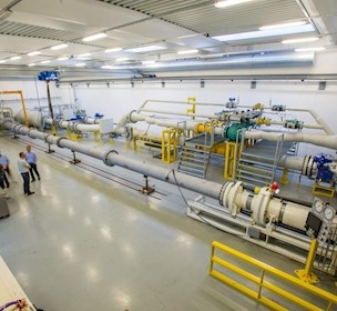
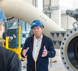
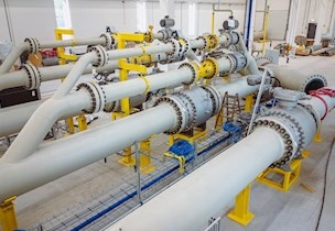
Facility
Accredited high-pressure flowmeter calibration 24/7
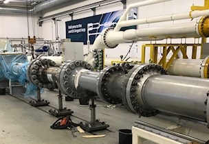
Facility
Accredited high-pressure flowmeter calibration 24/7
Related content

MEGA loop inaugurated
/News
EMCO Controls' choice for accurate calibration
/Case
Precise measuring instrumentation is imperative in the global custody transfer infrastructure.
High-pressure calibration of metering lines
/Case
Emerson are left with a verification that guarantees their customers accurate custody transfer.

MEGA loop revitalised
/News
The proportions of the MEGA loop will open up new possibilities for calibrating long meter systems.
Reducing operational uncertainty in gas transfers
/Article
Importance of managing fiscal risk in large volume gas custody transfer.
Uncertainty explained: Uncertainty budgets
/Article
Which factors are important to know and address when working with uncertainty budgets?
Uncertainty explained: How to calculate laboratory CMC?
/Article
What is CMC, and how does it involve the uncertainty of the laboratories?
E-guide: Understand calibration certificates
/Article
Learn how to read, interpret and understand gas calibration certificate with this e-guide.
Uncertainty explained: Class half meters
/Article
Most laboratories in the world don’t have uncertainty levels adequately low to perform accredited calibrations of a class half meter. How does this affect the gas metering industry?
5 arguments for re-calibration of gas meters
/Article
Why perform re-calibration of gas meters? 5 gas industry professionals share their opinion.